SWIFT® Evo Wheel Force Transducers
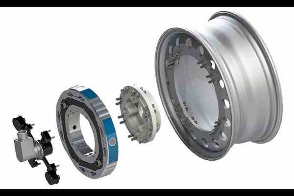
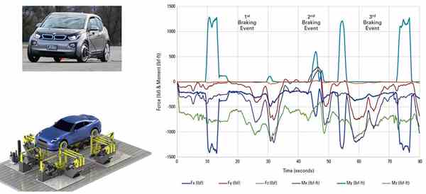
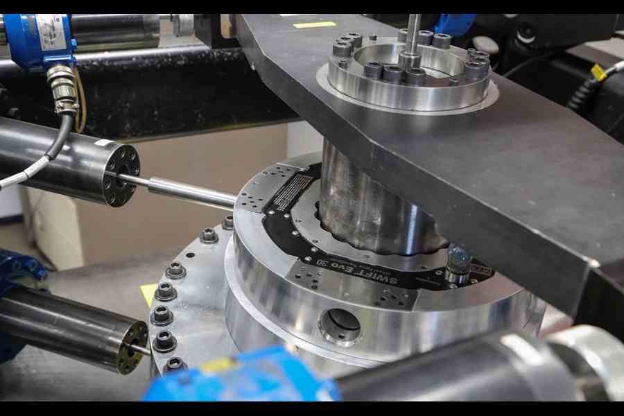
Ensure data measurement integrity throughout the entire vehicle durability testing process with accurate, robust and easy-to-use SWIFT Evo wheel force transducers. Ideal for spinning and non-spinning applications, they are used on the proving ground for Road Load Data Acquisition (RLDA), and in the test lab to iterate and play out RPC drive files on spindle-coupled road simulators. SWIFT Evo transducers employ a high-stiffness, one-piece design and a unique multi-axial calibration process to deliver unmatched measurement accuracy and long life.
Applications
- Durability
- Durability Test Load Generation
Test Specimens
- All-Terrain Vehicles
- Motorcycles
- Passenger Cars and SUVs
- Light Trucks
- Motorsport Vehicles
Key Product Features
Precise
Unparalleled measurement accuracy and integrity achieved with high-stiffness, one-piece design and multi-axial calibration
Robust / Durable
Fatigue-rated, machined from a forged billet of certified AMS high-strength, high-toughness aluminum or titanium
Easy-to-use
Intuitive Evo TI user interface and TEDS capabilities streamline and simplify set up, orientation and operation
Synchronized
Low end-to-end latency of 250 µsec enables tight synchronization with other transducers, sensors and active vehicle systems
Model Comparison
SWIFT Evo 10
Motorcycles & All-Terrain Vehicles (ATVs)
- Min Rim Size: 177.8 mm
- Al transducer weight: 1.2 kg
- Ti transducer weight: 1.9 kg
SWIFT Evo 20
Small & High-Performance Passenger Cars
- Min Rim Size: 304.8 mm
- Al transducer weight: 3.1 kg
- Ti transducer weight: 4.8 kg
SWIFT Evo 30
Medium-Large Passenger Cars & Minivans
- Min Rim Size: 330.2 mm
- Al transducer weight: 4.3 kg
- Ti transducer weight: 6.3 kg
SWIFT Evo 40
Light Trucks & Sport Utility Vehicles (SUVs)
- Min Rim Size: 381 mm
- Al transducer weight: 8.5 kg
- Ti transducer weight: 12.1 kg
Technical Overview
|
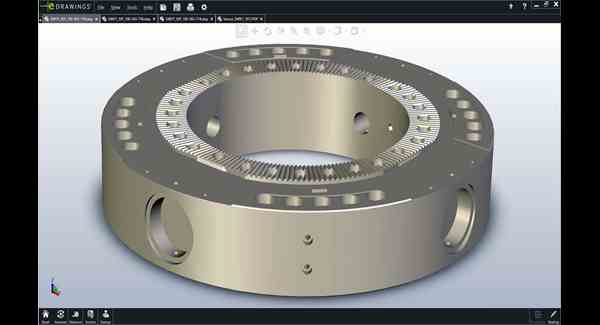
SWIFT Evo transducers achieve unparalleled measurement accuracy and long life by employing a high-stiffness, one-piece design machined from a forged billet of certified AMS high strength, high toughness aluminum or titanium alloy.
Unique among wheel force transducers, this proven design yields high sensitivity, excellent linear behavior, and high overload capacity. The transducers’ high natural frequency provides phase integrity between measured channels across the operating frequency range.
With no bolted joints, the one-piece design eliminates micro-slippage - the largest contributor to hysteresis - and facilitates efficient heat transfer across the sensor, minimizing temperature differentials in gaged areas.
The one-piece design also minimizes the number of required gages, which enhances transducer reliability and robustness.
A patented MTS flexure isolated shear beam decouples the transducer’s six components of measurement to reduce cross-coupling between measured axes. This increases transducer sensitivity to minute forces and moments and minimizes thermal response.
The one-piece outer ring and shear beam combine to make the SWIFT Evo insensitive to variations in stiffness among wheel rims and road simulator fixtures, facilitating easier integration with both.
SWIFT Evo transducers are testedto SAE J267 and J328 requirements, assuring a long life when properly maintained. Sealed to IP67 standards, they are virtually weather and contaminant proof.
SWIFT Evo transducers are fatigue rated, so the same unit can be deployed on a vehicle at the proving ground for RLDA and then in the lab for both drive file iteration and actual durability testing if desired. |
|
||||||||||
 |
|
||||||||||
|
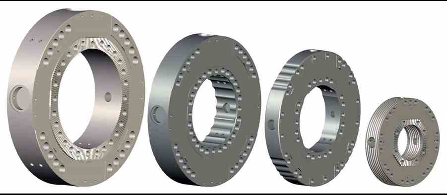
Download the CAD files (.step) below to explore how the robust, one-piece transducer design manifests across the SWIFT Evo portfolio – aluminum (a) and titanium (t). |
|||||||||||
| 40t | |||||||||||
|
|
|
||||||||||
|
|
|
||||||||||
|
The measurement accuracy of SWIFT Evo transducers is ensured through a multi-axial calibration process provided exclusively by MTS Metrology & Calibration.
While most wheel force transducers are calibrated one channel at a time, SWIFT Evo units are subject to a meticulous, automated process that calibrates the entire transducer, cycling through each channel while exciting all others. This approach enables precise measurements of cross-coupling coefficients under far more realistic loading conditions.
The calibrated SWIFT Evo wheel force transducer is capable of yielding data that can be shared across units with very high fidelity. This affords the flexibility to dedicate specific units for RLDA, drive file generation or durability testing, while maintaining data integrity across the process. |
|
 |
 |
 |
 |
||||||
|
Max Calibrated Load Ratings |
10Al |
10Ti |
20Al |
20Ti |
30Al |
30Ti |
40Al |
40Ti |
|
|
Longitudinal force (Fx) |
kN |
12 |
20 |
21 |
30 |
28 |
50 |
40 |
60 |
|
lb |
2,643 |
4,400 |
4,721 |
6,744 |
6,295 |
11,240 |
8,992 |
13,489 |
|
|
Lateral force (Fy) |
kN |
7 |
12 |
16 |
25 |
23 |
40 |
30 |
45 |
|
lb |
1,540 |
2,640 |
3,597 |
5,620 |
5,171 |
8,992 |
6,744 |
10,116 |
|
|
Vertical force (Fz) |
kN |
12 |
20 |
21 |
30 |
28 |
50 |
40 |
60 |
|
lb |
2,643 |
4,400 |
4,721 |
6,744 |
6,295 |
11,240 |
8,992 |
13,489 |
|
|
Overturning moment (Mx) |
kN-m |
1.6 |
3 |
4 |
6 |
5 |
9 |
9 |
15 |
|
lb-ft |
1,180 |
2,235 |
2,950 |
4,425 |
3,688 |
6,638 |
6,638 |
11,063 |
|
|
Driving/braking moment (My) |
kN-m |
2.2 |
3.5 |
5 |
8.5 |
7.5 |
13 |
13 |
20 |
|
lb-ft |
1,612 |
2,565 |
3,687 |
6,269 |
5,532 |
9,588 |
9,588 |
14,751 |
|
|
Steering moment (Mz) |
kN-m |
1.6 |
3 |
4 |
6 |
5 |
9 |
9 |
15 |
|
lb-ft |
1,180 |
2,235 |
2,950 |
4,425 |
3,688 |
6,638 |
6,638 |
11,063 |
|
| Operational Specifications | 10Al | 10Ti | 20Al | 20Ti | 30Al | 30Ti | 40Al | 40Ti | |
|
Noise Level peak-to-peak (0-500 Hz) |
N |
4 |
6 |
4 |
6 |
3 |
5 |
4 |
6 |
|
Max Usable RPM* |
RPM |
2400 |
2400 |
2400 |
2400 |
2400 |
2400 |
2400 |
2400 |
|
Max Operating Temperature |
°C |
125 |
125 |
125 |
125 |
125 |
125 |
125 |
125 |
|
°F |
257 |
257 |
257 |
257 |
257 |
257 |
257 |
257 |
|
|
Shock Resistance Each Axis |
G |
60 |
60 |
60 |
60 |
60 |
60 |
60 |
60 |
|
Environmental Protection Rating |
|
IP67 |
IP67 |
IP67 |
IP67 |
||||
|
Input Voltage Required |
VDC |
10-28 |
10-28 |
10-28 |
10-28 |
||||
|
Input Power Required per Transducer |
W |
6 |
6 |
6 |
6 |
||||
|
Output Voltage Full Scale Calibrated Load |
VDC |
±10 |
±10 |
±10 |
±10 |
||||
|
SAE J328 Half Axle Rating |
kg |
na
|
na
|
438 |
717 |
662 |
1,089 |
1,225 |
2,313 |
|
lb |
na
|
na
|
965 |
1,580 |
1,460 |
2,400 |
2,700 |
5,100 |
|
|
SAE Bending Moment seen on cell |
kN-m |
1.45 |
4.76 |
3.1 |
4.5 |
4.8 |
8.0 |
9.5 |
15.5 |
|
lb-ft |
1,072 |
3507 |
2,305 |
3,292 |
3,544 |
5,893 |
6,977 |
11,466 |
|
*3000 rpm for tests lasting less than 30 minutes and 200 mph cooling air
|
Specification % |
10Al |
10Ti |
20Al |
20Ti |
30Al |
30Ti |
40Al |
40Ti |
||
|
Nonlinearity |
Force |
%FS |
0.4 (0.2) |
0.4 (0.2) |
0.3 (0.15) |
0.3 (0.15) |
0.2 (0.15) |
0.2 (0.15) |
0.3 (0.15) |
0.3 (0.15) |
|
Moment |
%FS |
0.7 (0.2) |
0.7 (0.2) |
0.5 (0.2) |
0.5 (0.2) |
0.3 (0.2) |
0.3 (0.2) |
0.5 (0.2) |
0.5 (0.2) |
|
|
Hysteresis |
Force |
%FS |
(0.2) 0.2 |
(0.2) 0.2 |
(0.1) 0.2 |
(0.1) 0.2 |
(0.1) 0.2 |
(0.1) 0.2 |
(0.1) 0.2 |
(0.1) 0.2 |
|
Moment |
%FS |
(0.2) 0.5 |
(0.2) 0.5 |
(0.2) 0.3 |
(0.2) 0.3 |
(0.2) 0.3 |
(0.2) 0.3 |
(0.2) 0.3 |
(0.2) 0.5 |
|
|
Crosstalk |
Fy → Fx, Fz |
%FS |
0.6 (0.2) |
0.6 (0.2) |
0.4 (0.25) |
0.4 (0.25) |
0.25 (0.2) |
0.25 (0.2) |
0.2 (0.2) |
0.2 (0.2) |
|
Fx ←→ Fz |
%FS |
0.6 (0.2) |
0.6 (0.2) |
0.5 (0.25) |
0.5 (0.25) |
0.3 (0.2) |
0.3 (0.2) |
0.3 (0.2) |
0.3 (0.2) |
|
|
Fx, Fz → Fy |
%FS |
0.5 (0.2) |
0.5 (0.2) |
0.5 (0.3) |
0.5 (0.3) |
0.4 (0.2) |
0.4 (0.2) |
0.25 (0.2) |
0.25 (0.2) |
|
** “Typical Performance” listed is better than or equal to the median historical performance level
|
Assembly Information |
10Al |
10Ti |
20Al |
20Ti |
30Al |
30Ti |
40Al |
40Ti |
|
|
Transducer |
kg |
1.2 |
1.9 |
3.1 |
4.8 |
4.3 |
6.3 |
8.5 |
12.4 |
|
lb |
2.7 |
4.2 |
6.8 |
10.6 |
9.4 |
13.9 |
18.8 |
27.3 |
|
|
Min Rim Size |
mm |
177.8 |
177.8 |
304.8 |
304.8 |
330.2 |
330.2 |
381 |
381 |
|
in |
7 |
7 |
12 |
12 |
13 |
13 |
15 |
15 |
|
|
Typical Lug Nut Bolt Circle |
mm |
All |
Up to 120 |
Up to 120 |
Up to 170 |
||||
|
Type Connector Output |
|
BNC |
BNC |
BNC |
BNC |
||||
|
Auto Shunt Calibration |
|
on vehicle or test rig |
on vehicle or test rig | on vehicle or test rig | on vehicle or test rig | ||||
|
Modal Properties: Frequency |
10Al |
10Ti |
20Al |
20Ti |
30Al |
30Ti |
40Al |
40Ti |
||
|
With Tire & Rim |
Mx, My |
Hz |
na | na |
325 |
na |
385 |
425 |
470 |
480 |
|
Fy |
Hz |
na | na |
610 |
na |
675 |
765 |
740 |
770 |
|
|
Without Tire & Rim |
My Mx, |
Hz |
na | na |
980 |
na |
845 |
810 |
810 |
775 |
|
Fy |
Hz |
na | na |
1,575 |
na |
1,255 |
1,445 |
1,490 |
1,570 |
|
Notes:
- Specifications are subject to change without notice.
- Based on loads at the center of the transducer.
- Each SWIFT Evo transducer will be calibrated on an MTS calibration machine. MTS provides complete documentation of calibration values by serial number for each SWIFT Evo unit. Unique calibration values are stored *electronically and transferred to the transducer interface box (Evo TI box) shipped with each SWIFT Evo system.
- Periodic recalibration services can be provided by MTS.
- MTS can manufacture rims designed in accordance with SAE J328 criteria. Proper rim design is essential for optimum performance.
|
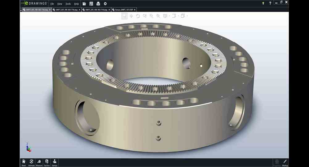
SWIFT Evo wheel force transducers achieve unparalleled measurement accuracy and long life by employing a high-stiffness, one-piece design machined from a forged billet of certified AMS high strength, high toughness aluminum or titanium alloy.
Download the CAD files (.step) below to explore how the robust, one-piece transducer design manifests across the SWIFT Evo portfolio – aluminum (a) and titanium (t). |
 |
|||||||
|
|
||||||||
SWIFT Evo Wheel Force Transducer Brochure SWIFT Evo Services Brochure
Service and Support
Our experts are here to help keep you up and running.
Related Products, Parts or Accessories
RPC® Connect Software
FlexTest® Controllers
Flat-Trac® Tire Force & Moment Measurement Systems
Flat-Trac Handling Roadway
Looking for more products?
Go to Solution FinderContact An MTS Rep Today
Ready for a quote or need more information? We're here to help. Request a quoteResources
Introducing FlexTest Elite Performance Controllers
Increase channel count, system rate and computational cap…
The Road to RPC Connect
Cody Johnson explores RPC software - past, present and futur…
The Origins of RPC with Dr. Glen Grenier
Q&A with the durability testing pioneer on the rise of R…
RPC Connect Software Preview: Webinar 1
Safa Mogharebi explores the new Graphical User Interface
RPC Connect Software Preview: Webinar 2
Safa Mogharebi explores the new Setup & Analyze Stages
RPC Connect Software Preview: Webinar 3
Safa Mogharebi explores the new Model & Simulate Stages
RPC Connect Software Preview: Webinar 4
Safa Mogharebi explores the new Test Stage

